Elite HVAC Manual-J Load Calculation – Explanation of Reports
Elite HVAC Manual-J Load Calculation – Explanation of Reports
Load Preview Report – This report shows gain, loss and CFM values for the building and each system, zone and room in the project.
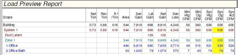
Net Ton: Shows the tonnage calculated by simply adding the sensible and latent cooling loads.
Rec Ton: Shows the tonnage calculated by determining the capacity required to meet both the sensible and latent gains, according to the Percent Sensible Capacity of each system.
ft² / Ton: Shows the square feet per ton at the building and system levels. The tonnage used here is the recommended tonnage, as described above.
Area: Square foot of conditioned space
Gain represents cooling loads, Loss represent heating loads.
Sen Gain: Sensible gain, in Btuh. Lat Gain: Latent gain, in Btuh.
Net Gain: Sensible plus latent gain, in Btuh. Sen Loss: Sensible loss in Btuh.
Min Htg CFM: Minimum heating CFM requirement, based on the sensible loss.
Min Clg CFM: Same as Min Htg CFM column, but for cooling.
Sys Htg CFM: Shows the building cfm based on equipment chosen (400 cfm per ton). Also shows the room or zone's portion of the system CFM, based on the ratio of the room or zone's sensible loss to that of the system. The value in this column is highlighted in yellow if it is larger than cooling, otherwise the value in the Sys Clg CFM will be highlighted.
Sys Clg CFM: Same as Sys Htg CFM column, but for cooling.
Sys Act CFM: The actual CFM delivered. Depending on the setting of the Airflow Option input, this value will equal either the Sys Htg CFM or the Sys Clg CFM column.
TOTAL BUILDING SUMMARY LOADS - This report identifies the building materials that were entered into the program to calculate the building load.
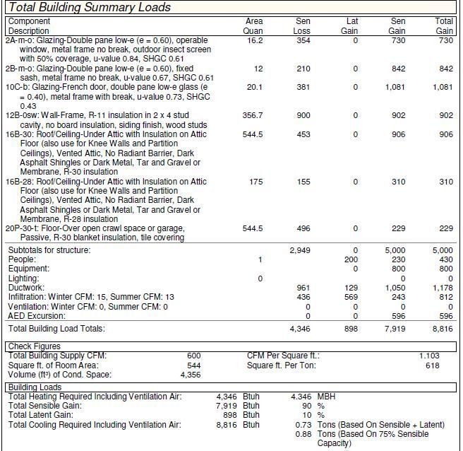
Component Description - A description of the building materials. The windows, doors, walls, roof/attic, and floor types used in the building.
Area Quan - Area of each of these components, in sq ft.
Sen Loss - Sensible loss, the heating load of the component.
Lat Gain - Latent gain is water vapor that comes from people’s breath and skin, cooking, showers, laundry and building leakage. Note that building components do not have any latent gain. Latent gain is part of the building’s cooling load.
Sen Gain - The heat gain associated with the temperature of the air is called the Sensible Heat Gain. Sensible gain is also used in the calculation of the cooling load.
Total Gain - Latent gain plus Sensible gain.
After the Subtotals for Structure are the things that are added to the load such as people, lighting, equipment loads and a duct load, based on the duct location. This section also notes the amount of estimated building infiltration and the amount of ventilation based on number of people and sq ft of the building.
Total Building Load Totals - All factors are added up to give the necessary btu of heating and cooling.
Check Figures - shows the building cfm. This is based on the size of the air conditioning system. The industry standard is 400 cfm per ton. The volume is the room area x the height of the room. The cfm per ton and square ft per ton are based on the loads and the building cfm input for the equipment size.
Building loads - the btu required for the building. This includes the heating required including ventilation air, the total sensible gain and total latent gain which will give the total required for the building. It then breaks this down to show the % of each. The final breakdown shows the recommended tonnage based on a 75% sensible capacity. The majority of equipment available has a 75% sensible removal ability (SHR Sensible Heat Ratio).
Additional Guidelines
1) Size the cooling equipment based on the total sensible heat gain and total net heat gain listed in the building summary load section. In most cases, if the equipment meets the sensible heat gain, then it will also meet the latent heat gain.
2) In the same manner, size the heating equipment based on the total sensible heat loss listed in the summary load section.
3) Duct sizing should be performed using an ACCA “Manual D” duct sizing program to design the proper duct system. Duct lengths, duct types, blower performance, filters, coils, and diffusers all play a part in determining the proper size trunk lines and run-outs.
4) Base the duct system on which is greater, the required heating CFM or the required cooling CFM. The actual room by room system CFM listed on the room load summary reflects the greater of the two.
Share a Blog Post
STATE CERT. CAC027359
Location
121 Triple Diamond Blvd, Unit #16
North Venice, FL 34275